出典:パソコン上のM5Stackの3Dモデルを、M5Stackの動きに合わせて動かす
(1)パソコン上にM5Stackの3Dモデルを作成
(2)IMUを使い端末の姿勢を計算
(3)姿勢データをパソコンに送り、3Dモデルを制御
続きの(3)の手順から始める。
姿勢データをパソコンにBlueToothで送信
前回は、MPU6886なのでyawの値の計算値がおかしく、途中であきらめたが、ローリング、ピッチングだけでも3Dモデルを制御してみることに。
やっているのは出典サイトの内容をなぞっただけ。
Bluetooth経由でパソコンとシリアル通信を行うため、赤字部分を追加している。
M5C2_MPU6886_Serialプロジェクト
VScode+PlatFormIOの環境で、M5C2へ書き込む。
main.cpp
#include <M5Core2.h>
#include <BluetoothSerial.h>
BluetoothSerial SerialBT;
float accX = 0.0F;
float accY = 0.0F;
float accZ = 0.0F;
float gyroX = 0.0F;
float gyroY = 0.0F;
float gyroZ = 0.0F;
float pitch = 0.0F;
float roll  = 0.0F;
float yaw   = 0.0F;

void setup(){
  M5.begin();
  SerialBT.begin("M5StackCore2"); //Bluetoothデバイス名
  //パソコン側で「M5StackCore2」の名前のデバイスとペアリングをすること。
  M5.IMU.Init();
  M5.Lcd.fillScreen(BLACK);
  M5.Lcd.setTextColor(GREEN , BLACK);
  M5.Lcd.setTextSize(2);
}

void loop() {
  M5.IMU.getGyroData(&gyroX,&gyroY,&gyroZ);
  M5.IMU.getAccelData(&accX,&accY,&accZ);
  M5.IMU.getAhrsData(&pitch,&roll,&yaw);
  M5.Lcd.setCursor(0, 20);
  M5.Lcd.printf("gyroX,  gyroY,  gyroZ");
  M5.Lcd.setCursor(0, 42);
  M5.Lcd.printf("%6.2f %6.2f%6.2f o/s", gyroX, gyroY, gyroZ);
  M5.Lcd.setCursor(0, 70);
  M5.Lcd.printf("accX,   accY,  accZ");
  M5.Lcd.setCursor(0, 92);
  M5.Lcd.printf("%5.2f  %5.2f  %5.2f G", accX, accY, accZ);
  M5.Lcd.setCursor(0, 120);
  M5.Lcd.printf("pitch,  roll,  yaw");
  M5.Lcd.setCursor(0, 142);
  M5.Lcd.printf("%5.2f  %5.2f  %5.2f deg", pitch, roll, yaw);
  Serial.printf("%5.2f,%5.2f,%5.2f\r\n", pitch, roll, yaw);
  SerialBT.printf("%5.2f,%5.2f,%5.2f\r\n", pitch, roll, yaw);
  delay(10);
}
3Dモデルを制御するProcessing側スケッチ
M5Core2_Serialスケッチ
M5Core2_Serial.pde
PImage front, back, right, left, top, bottom;
import processing.serial.*;
Serial port;
void setup() {
size(1200, 800, P3D);
front = loadImage("front.jpg");
back = loadImage("back.jpg");
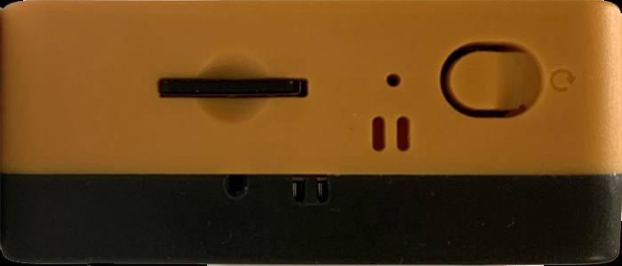
right = loadImage("right.jpg");
left = loadImage("left.jpg");
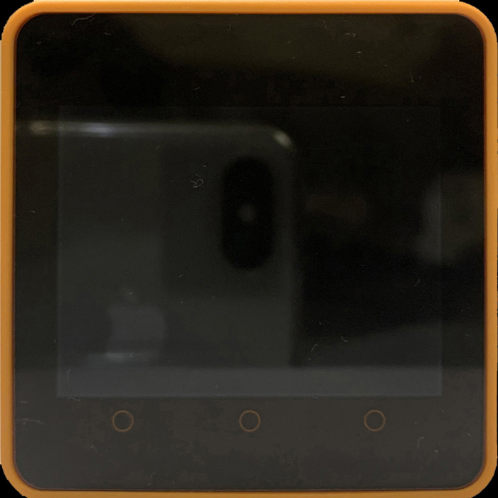
top = loadImage("top.jpg");
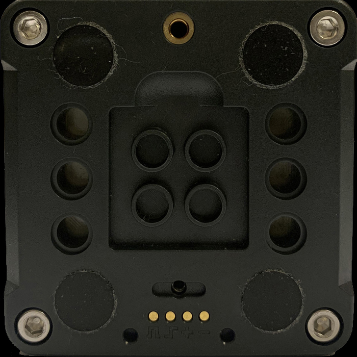
bottom = loadImage("bottom.jpg");
textureMode(IMAGE);
String[] ports = Serial.list();
//BlueToothの通信COMポートを探す必要があるので、確認にはTeratermが便利。
for (int i = 0; i < ports.length; i++) {
println(i + ": " + ports[i]);
}
//たまたま自分の環境ではports[4]だったが、パソコンとのUSB
接続ケーブルを外すと、ports[3]に変わるので結構面倒。
port = new Serial(this, ports[4], 115200);
}
void draw() {
if (port.available() == 0) return;
String str = port.readStringUntil('\n');
if (str == null) return;
String toks[] = split(trim(str), ",");
if (toks.length != 3) return;
float pitch = float(toks[0]);
float roll = float(toks[1]);
float yaw = 180 - float(toks[2]); //出典に合わせただけ?
print(yaw); print(", ");
print(pitch); print(", ");
println(roll);
background(0);
translate(width / 2, height / 2);
scale(0.4);
pushMatrix();
float cr = cos(radians(roll));
float sr = sin(radians(roll));
float cp = cos(radians(pitch));
float sp = sin(radians(pitch));
float cy = cos(radians(yaw));
float sy = sin(radians(yaw));
//rolling
// applyMatrix( 1, 0, 0, 0,
// 0, cr, sr, 0,
// 0, -sr, cr, 0,
// 0, 0, 0, 1);
//pitching
// applyMatrix( cp, -sp, 0, 0,
// sp, cp, 0, 0,
// 0, 0, 1, 0,
// 0, 0, 0, 1);
//yawing
// applyMatrix( cy, 0, -sy, 0,
// 0, 1, 0, 0,
// sy, 0, cy, 0,
// 0, 0, 0, 1);
//pitching<rolling
// applyMatrix(cp, -sp*cr, -sp*sr, 0,
// sp, cp*cr, cp*sr, 0,
// 0, -sr, cr, 0,
// 0, 0, 0, 1);
//yawing<pitching<rolling
applyMatrix(cy*cp, -cy*sp*cr+sy*sr, -cy*sp*sr-sy*cr, 0,
sp, cp*cr, cp*sr, 0,
sy*cp, -sy*sp*cr-cy*sr, -sy*sp*sr+cy*cr, 0,
0, 0, 0, 1);
drawM5Core2();
popMatrix();
// saveFrame("frames/######.png");
}
void drawM5Core2() {
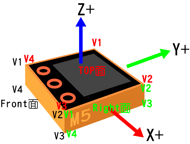
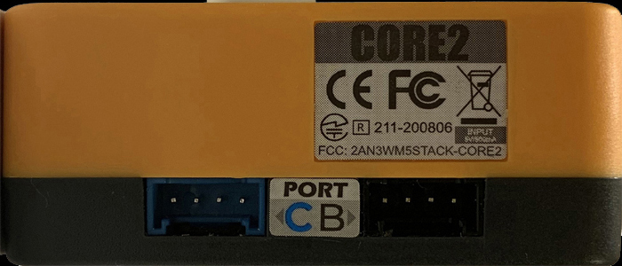
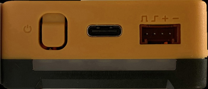
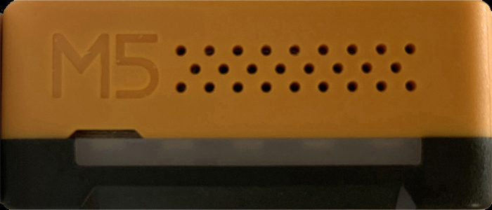
//立方体各面の、左上をV1としコの字形にV1,V2,V3,V4の順に各頂点の座標を求めている。
//画像のUV座標はV1を原点(0,0)とし、横U軸側右に700、縦V軸側下に300のように決めている。
beginShape();
texture(front);
vertex(-350, -150, 350, 0, 0); //V1
vertex( 350, -150, 350, 700, 0); //V2
vertex( 350, 150, 350, 700, 300); //V3
vertex(-350, 150, 350, 0, 300); //V4
endShape();
beginShape();
texture(back);
vertex( 350, -150, -350, 0, 0); //V1
vertex(-350, -150, -350, 700, 0); //V2
vertex(-350, 150, -350, 700, 300); //V3
vertex( 350, 150, -350, 0, 300); //V4
endShape();
beginShape();
texture(right);
vertex( 350, -150, 350, 0, 0); //V1
vertex( 350, -150, -350, 700, 0); //V2
vertex( 350, 150, -350, 700, 300); //V3
vertex( 350, 150, 350, 0, 300); //V4
endShape();
beginShape();
texture(left);
vertex(-350, -150, -350, 0, 0); //V1
vertex(-350, -150, 350, 700, 0); //V2
vertex(-350, 150, 350, 700, 300); //V3
vertex(-350, 150, -350, 0, 300); //V4
endShape();
beginShape();
texture(top);
vertex(-350, -150, -350, 0, 0); //V1
vertex( 350, -150, -350, 700, 0); //V2
vertex( 350, -150, 350, 700, 700); //V3
vertex(-350, -150, 350, 0, 700); //V4
endShape();
beginShape();
texture(bottom);
vertex( 350, 150, -350, 0, 0); //V1
vertex(-350, 150, -350, 700, 0); //V2
vertex(-350, 150, 350, 700, 700); //V3
vertex( 350, 150, 350, 0, 700); //V4
endShape();
}dataフォルダにはみっともない画
動かした結果がこれ
パソコンの能力が低く、pngを書き込むと画像がカクカク動くお粗末さ。
回転行列など年寄りには無理なこと、もともとの頭の悪さはいかんともしがたく、理論などもっての他、しかたがないのでこれにて終了。
やはり、常にyaw軸回りに左回転をしていて思うように動かせないままだが。