自分が使っているのはM5Stack Core2 for AWSなので、M5Stack Core2+M5GO Bottom2のスタック。
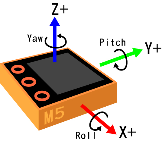
MPU6886はM5GO Bottom2側にあり、軸の向きが分からず動かしながら調べた結果がこれ、よく分かっていないので間違っているかも。
MPU6886:6軸IMUユニットのサンプルプログラム
#include <M5Core2.h>
float accX = 0.0F;  // Define variables for storing inertial sensor data
float accY = 0.0F;
float accZ = 0.0F;
float gyroX = 0.0F;
float gyroY = 0.0F;
float gyroZ = 0.0F;
float pitch = 0.0F;
float roll  = 0.0F;
float yaw   = 0.0F;
float temp = 0.0F;
/* After M5Core2 is started or reset
the program in the setUp () function will be run, and this part will only be run once.
 */
void setup(){
  M5.begin(); //Init M5Core.
  M5.IMU.Init();  //Init IMU sensor.
  M5.Lcd.fillScreen(BLACK); //Set the screen background color to black.
  M5.Lcd.setTextColor(GREEN , BLACK); //Sets the foreground color and background color of the displayed text.
  M5.Lcd.setTextSize(2);  //Set the font size.
}

void loop() {
//Stores the triaxial gyroscope data of the inertial sensor to the relevant variable
  M5.IMU.getGyroData(&gyroX,&gyroY,&gyroZ);
  M5.IMU.getAccelData(&accX,&accY,&accZ); //Stores the triaxial accelerometer.
  M5.IMU.getAhrsData(&pitch,&roll,&yaw);  //Stores the inertial sensor attitude.
  M5.IMU.getTempData(&temp);  //Stores the inertial sensor temperature to temp.
//gyroscope output related.
  M5.Lcd.setCursor(0, 20);  //Move the cursor position to (x,y).
  M5.Lcd.printf("gyroX,  gyroY,  gyroZ"); //Screen printingformatted string.
  M5.Lcd.setCursor(0, 42);
  M5.Lcd.printf("%6.2f %6.2f%6.2f o/s", gyroX, gyroY, gyroZ);
// Accelerometer output is related
  M5.Lcd.setCursor(0, 70);
  M5.Lcd.printf("accX,   accY,  accZ");
  M5.Lcd.setCursor(0, 92);
  M5.Lcd.printf("%5.2f  %5.2f  %5.2f G", accX, accY, accZ);
// Pose output is related
  M5.Lcd.setCursor(0, 120);
  M5.Lcd.printf("pitch,  roll,  yaw");
  M5.Lcd.setCursor(0, 142);
  M5.Lcd.printf("%5.2f  %5.2f  %5.2f deg", pitch, roll, yaw);
// Inertial sensor temperature output related
  M5.Lcd.setCursor(0, 175);
  M5.Lcd.printf("Temperature : %.2f C", temp);
  delay(100);  // Delay 10ms.
}
コードの意味
中味を少しは理解しようと試みたがとても無理、初めのこのコードで挫折。
M5.IMU.getGyroData(&gyroX,&gyroY,&gyroZ);
MPU6886.h
#define MPU6886_ADDRESS           0x68
#define MPU6886_WHOAMI            0x75
#define MPU6886_ACCEL_INTEL_CTRL  0x69
#define MPU6886_SMPLRT_DIV        0x19
#define MPU6886_INT_PIN_CFG       0x37
#define MPU6886_INT_ENABLE        0x38
#define MPU6886_GYRO_XOUT_H       0x43
#define MPU6886_USER_CTRL         0x6A
#define MPU6886_PWR_MGMT_1        0x6B
#define MPU6886_PWR_MGMT_2        0x6C
#define MPU6886_CONFIG            0x1A
#define MPU6886_GYRO_CONFIG       0x1B
#define MPU6886_ACCEL_CONFIG      0x1C
#define MPU6886_ACCEL_CONFIG2     0x1D
#define MPU6886_FIFO_EN           0x23
class MPU688{
    public:
      enum Ascale {
        AFS_2G = 0,
        AFS_4G,
        AFS_8G,
        AFS_16G
      };
      enum Gscale {
        GFS_250DPS = 0,
        GFS_500DPS,
        GFS_1000DPS,
        GFS_2000DPS
      };
      Gscale Gyscale = GFS_2000DPS; //Gyscale初期値
      Ascale Acscale = AFS_8G; //Acscale初期値
ジャイロのフルスケールを選択、GFS_2000DPSが既定値。
gRes = 2000.0/32768.0で、7bitで割ることで基準値gResを算出?
DPS=毎秒度(o/s)、±を考慮して7bit?
MPU6886.cpp
void MPU6886::getGres(){
   switch (Gyscale)
   {
  // Possible gyro scales (and their register bit settings) are:
     case GFS_250DPS:
           gRes = 250.0/32768.0;
           break;
     case GFS_500DPS:
           gRes = 500.0/32768.0;
           break;
     case GFS_1000DPS:
           gRes = 1000.0/32768.0;
           break;
     case GFS_2000DPS:
           gRes = 2000.0/32768.0;
           break;
   }
}

void MPU6886::getAres(){
   switch (Acscale)
   {
   // Possible accelerometer scales (and their register bit settings) are:
   // 2 Gs (00), 4 Gs (01), 8 Gs (10), and 16 Gs  (11).
   // Here's a bit of an algorith to calculate DPS/(ADC tick) based on that 2-bit value:
    case AFS_2G:
          aRes = 2.0/32768.0;
          break;
    case AFS_4G:
          aRes = 4.0/32768.0;
          break;
    case AFS_8G:
          aRes = 8.0/32768.0;
          break;
    case AFS_16G:
          aRes = 16.0/32768.0;
          break;
  }
}
void MPU6886::getGyroData(float* gx, float* gy, float* gz){
int16_t gyroX = 0;
int16_t gyroY = 0;
int16_t gyroZ = 0;
getGyroAdc(&gyroX,&gyroY,&gyroZ);
*gx = (float)gyroX * gRes;
*gy = (float)gyroY * gRes;
*gz = (float)gyroZ * gRes;
}
void MPU6886::getGyroAdc(int16_t* gx, int16_t* gy, int16_t* gz){
uint8_t buf[6];
I2C_Read_NBytes(MPU6886_ADDRESS,MPU6886_GYRO_XOUT_H,6,buf);
*gx=((uint16_t)buf[0]<<8)|buf[1];
*gy=((uint16_t)buf[2]<<8)|buf[3];
*gz=((uint16_t)buf[4]<<8)|buf[5];
} やっていることは、各軸の角速度o/sをジャイロから読んでいるだけ
(1)I2CでMPU6886のMPU6886_GYRO_XOUT_Hレジスタから始まる6バイトを読み込む。
(2)それを2バイトずつHバイト<<8+Lバイトを結合しuint16にする。
(3)更にgResを掛けてジャイロの*gx,*gy,*gzを求め、gyroX,gyroY,gyroZに代入。
(4)加速度も全く同じでM5.IMU.getAccelData(&accX,&accY,&accZ);に変わるだけ。
M5.IMU.getAhrsData(&pitch,&roll,&yaw);
MPU6886.cpp
void MPU6886::getAhrsData(float *pitch,float *roll,float *yaw){
  float accX = 0;
  float accY = 0;
  float accZ = 0;
  float gyroX = 0;
  float gyroY = 0;
  float gyroZ = 0;
  getGyroData(&gyroX,&gyroY,&gyroZ);
  getAccelData(&accX,&accY,&accZ);
  MahonyAHRSupdateIMU(gyroX * DEG_TO_RAD, gyroY * DEG_TO_RAD, gyroZ * DEG_TO_RAD, accX, accY, accZ,pitch,roll,yaw);
}
MahonyAHRS.cpp
こちらに至っては手も足もでない、ピッチ、ロール、ヨーの算出をしているようだが、全く分からず諦めることに。
// IMU algorithm update
void MahonyAHRSupdateIMU(float gx, float gy, float gz, float ax, float ay, float az,float *pitch,float *roll,float *yaw) {
	float recipNorm;
	float halfvx, halfvy, halfvz;
	float halfex, halfey, halfez;
	float qa, qb, qc;
	// Compute feedback only if accelerometer measurement valid (avoids NaN in accelerometer normalisation)
	if(!((ax == 0.0f) && (ay == 0.0f) && (az == 0.0f))) {
		// Normalise accelerometer measurement
		recipNorm = invSqrt(ax * ax + ay * ay + az * az);
		ax *= recipNorm;
		ay *= recipNorm;
		az *= recipNorm;
		// Estimated direction of gravity and vector perpendicular to magnetic flux
        volatile float q0 = 1.0, q1 = 0.0, q2 = 0.0, q3 = 0.0;
		halfvx = q1 * q3 - q0 * q2;
		halfvy = q0 * q1 + q2 * q3;
		halfvz = q0 * q0 - 0.5f + q3 * q3;
		// Error is sum of cross product between estimated and measured direction of gravity
		halfex = (ay * halfvz - az * halfvy);
		halfey = (az * halfvx - ax * halfvz);
		halfez = (ax * halfvy - ay * halfvx);
		// Compute and apply integral feedback if enabled
		if(twoKi > 0.0f) {
			integralFBx += twoKi * halfex * (1.0f / sampleFreq);	// integral error scaled by Ki
			integralFBy += twoKi * halfey * (1.0f / sampleFreq);
			integralFBz += twoKi * halfez * (1.0f / sampleFreq);
			gx += integralFBx;	// apply integral feedback
			gy += integralFBy;
			gz += integralFBz;
		}
		else {
			integralFBx = 0.0f;	// prevent integral windup
			integralFBy = 0.0f;
			integralFBz = 0.0f;
		}
		// Apply proportional feedback
		gx += twoKp * halfex;
		gy += twoKp * halfey;
		gz += twoKp * halfez;
	}
	// Integrate rate of change of quaternion
	gx *= (0.5f * (1.0f / sampleFreq));// pre-multiply common factors
	gy *= (0.5f * (1.0f / sampleFreq));
	gz *= (0.5f * (1.0f / sampleFreq));
	qa = q0;
	qb = q1;
	qc = q2;
	q0 += (-qb * gx - qc * gy - q3 * gz);
	q1 += (qa * gx + qc * gz - q3 * gy);
	q2 += (qa * gy - qb * gz + q3 * gx);
	q3 += (qa * gz + qb * gy - qc * gx);

	// Normalise quaternion
	recipNorm = invSqrt(q0 * q0 + q1 * q1 + q2 * q2 + q3 * q3);
	q0 *= recipNorm;
	q1 *= recipNorm;
	q2 *= recipNorm;
	q3 *= recipNorm;
	*pitch = asin(-2 * q1 * q3 + 2 * q0* q2);	// pitch
	*roll  = atan2(2 * q2 * q3 + 2 * q0 * q1, -2 * q1 * q1 - 2 * q2* q2 + 1);	// roll
	*yaw   = atan2(2*(q1*q2 + q0*q3),q0*q0+q1*q1-q2*q2-q3*q3);	//yaw
	*pitch *= RAD_TO_DEG;
    *yaw   *= RAD_TO_DEG;
    // Declination of SparkFun Electronics (40°05'26.6"N 105°11'05.9"W) is
    // 	8° 30' E  ± 0° 21' (or 8.5°) on 2016-07-19
    // - http://www.ngdc.noaa.gov/geomag-web/#declination
    *yaw   -= 8.5;
    *roll  *= RAD_TO_DEG;
	///Serial.printf("%f    %f    %f \r\n",  pitch, roll, yaw);
}
M5.IMU.Init()
M5.IMU.Init(); の初期化部分も、訳が分からず途中であきらめた。
regdata = 0x00; //MPU6886_PWR_MGMT_1 パワーマネジメント1レジスタに0x00書き込み
I2C_Write_NBytes(MPU6886_ADDRESS, MPU6886_PWR_MGMT_1, 1, ®data);
delay(10);
regdata = (0x01<<7);//同レジスタに0b10000000書き込み:リセット
I2C_Write_NBytes(MPU6886_ADDRESS, MPU6886_PWR_MGMT_1, 1, ®data);
delay(10);
regdata = (0x01<<0); //クロックAutoSelect
I2C_Write_NBytes(MPU6886_ADDRESS, MPU6886_PWR_MGMT_1, 1, ®data);
delay(10);
regdata = 0x10; //フルスケールを±8gに
I2C_Write_NBytes(MPU6886_ADDRESS, MPU6886_ACCEL_CONFIG, 1, ®data);
delay(1);
regdata = 0x18; //0b00011000 フルスケールを ±2000 dps.
I2C_Write_NBytes(MPU6886_ADDRESS, MPU6886_GYRO_CONFIG, 1, ®data);
delay(1);
regdata = 0x01; //これ以上は分からない
I2C_Write_NBytes(MPU6886_ADDRESS, MPU6886_CONFIG, 1, ®data);
delay(1);MPU-6886データシート p30/59
| ADDR (HEX) | ADDR (DEC.) | REGISTER NAME | SERIAL I/F | BIT7 |
|---|---|---|---|---|
| 43 | 67 | GYRO_XOUT_H | READ | GYRO_XOUT[15:8] |
| 44 | 68 | GYRO_XOUT_L | READ | GYRO_XOUT[7:0] |
| 45 | 69 | GYRO_YOUT_H | READ | GYRO_YOUT[15:8] |
| 46 | 70 | GYRO_YOUT_L | READ | GYRO_YOUT[7:0] |
| 47 | 71 | GYRO_ZOUT_H | READ | GYRO_ZOUT[15:8] |
| 48 | 72 | GYRO_ZOUT_L | READ | GYRO_ZOUT[7:0] |